
The OR gate is a fundamental building block in digital electronics. It implements logical addition, producing a high output (1) when at least one of its inputs is high.
This tutorial explains the working, truth table, symbol, logical expression, and applications of the OR gate.
What is an OR Gate?
An OR gate is a digital logic gate that outputs a 1 (high) if one or more of its inputs are 1. If all inputs are 0, the output is 0. It performs the logical addition (OR operation).
OR Gate Symbol
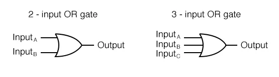
The OR gate is represented by a distinctive symbol in circuit diagrams, which looks like a curved shape tapering to a point at the output.
Two and Three Input OR Gate Symbol
Truth Table of an OR Gate
The truth table lists all possible input combinations and their corresponding output for an OR gate.
Two-Input OR Gate Truth Table
| Input A | Input B | Output Y |
|---|---|---|
| 0 | 0 | 0 |
| 0 | 1 | 1 |
| 1 | 0 | 1 |
| 1 | 1 | 1 |
Three-Input OR Gate Truth Table
| Input A | Input B | Input C | Output Y |
|---|---|---|---|
| 0 | 0 | 0 | 0 |
| 0 | 0 | 1 | 1 |
| 0 | 1 | 0 | 1 |
| 0 | 1 | 1 | 1 |
| 1 | 0 | 0 | 1 |
| 1 | 0 | 1 | 1 |
| 1 | 1 | 0 | 1 |
| 1 | 1 | 1 | 1 |
Logical Expression for an OR Gate
The logical expression for an OR gate can be written as:
Two-Input OR Gate
Y=A+B
Where:
- A,B: Inputs
- Y: Output
Three-Input OR Gate
Y=A+B+C
In Boolean algebra, the plus sign (+) represents the OR operation.
OR Gate Operation
The OR gate works by checking whether at least one of its inputs is 1:
- If any input is 1, the output is 1.
- If all inputs are 0, the output is 0.
Constructing an OR Gate Using Switches
An OR gate can be physically implemented using switches.
Example with Two Inputs
- Connect two switches A and B in parallel.
- When any switch is closed, the circuit is complete, and the output is high.
This parallel connection mirrors the behavior of the OR gate.
OR Gate Using ICs
Integrated circuits (ICs) provide multiple OR gates in a single package.
Popular ICs for OR Gates
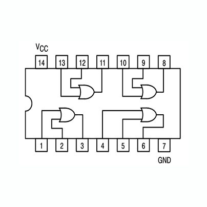
- IC 7432:
- A quad 2-input OR gate IC.
- Contains 4 independent OR gates, each with 2 inputs.
- Pin Configuration of IC 7432:
- Pins 1, 2: Inputs for Gate 1
- Pin 3: Output for Gate 1
- Pins 4, 5: Inputs for Gate 2
- Pin 6: Output for Gate 2
- Pin 14: VCC
- Pin 7: GND
Circuit Using IC 7432
- Connect power supply to Pin 14 (VCC) and Pin 7 (GND).
- Apply input signals to the respective input pins.
- Observe the output on the corresponding output pins.
Practical Example of an OR Gate
Security Alarm System
In a security system:
- A=Window sensor
- B=Door sensor
The alarm triggers if:
- The window sensor is activated (A=1).
- The door sensor is activated (B=1).
Using an OR gate:
Y=A+B
Truth Table for the Alarm System:
| Window Sensor (AA) | Door Sensor (BB) | Alarm (YY) |
|---|---|---|
| 0 | 0 | 0 |
| 0 | 1 | 1 |
| 1 | 0 | 1 |
| 1 | 1 | 1 |
OR Gate vs AND Gate
| Feature | OR Gate | AND Gate |
|---|---|---|
| Logical Operation | Logical addition (++) | Logical multiplication (⋅\cdot) |
| Output Condition | High if any input is high. | High only if all inputs are high. |
| Truth Table | Outputs 1 for 1+0,0+1,1+11+0, 0+1, 1+1. | Outputs 1 only for 1⋅11 \cdot 1. |
Boolean Algebra Simplification Using OR Gate
The OR gate is commonly used in Boolean algebra to simplify logical expressions.
Example:
Simplify Y=A⋅(B+C)+A⋅B
Solution:
- Apply distributive law: Y=A⋅B+A⋅C+A⋅B
- Combine like terms: Y=A⋅B+A⋅C
- Simplified result: Y=A⋅(B+C)
The OR operation plays a key role in such simplifications.
Advantages of OR Gate
- Simple to design and use.
- Versatile for many applications like alarms, sensors, and decision-making circuits.
- Easy to implement using ICs or physical switches.
Conclusion
The OR gate is a fundamental logic gate with versatile applications in digital circuits. By understanding its truth table, logical operation, and applications, you gain a strong foundation for designing and analyzing digital systems