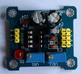
In this article we look at a NE555 adjustable pulse generator which can be purchased as a kit, board and components
Specs
Input voltage: 5 volts to 15 volts DC. 5 volts power supply, the output current can about 15 mA; with a 12 volts power supply, the output current can be up to 35 mA
-Input Current: 100 mA
-Output amplitude: 4.2 volts V-PP to 11.4v V-PP (depending on the input voltage, the output amplitude is not the same)
-Maximum output current: 15 mA (5V power supply, V-PP greater than 50%), 35 mA (12 volts power supply, V-PP greater than 50%)
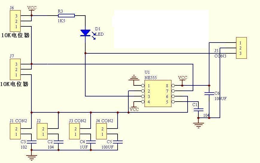
You can short and use one of the capacitors in the circuit, there are 4 options
1Hz ~ 50Hz
50Hz ~ 1kHz
1KHz ~ 10kHz
10kHz ~ 200kHz
Schematic
Parts List
Start with the resistor, ceramic capacitors, socket and then I soldered on the electrolytics, headers and potentiometers
The header needs to be cut up, I received a 11 way single pin header which I cut into 3.
I did receive the wrong value of cap
| component | label | value | Quantity |
| resistor | R1 | 1.5k | 1 |
| Ceramic capacitor | C1,C2 | 104 – 0.1uF | 2 |
| Ceramic capacitor | C3 | 102 – 0.001uF | 1 |
| 5 mm red LED | D1 | 1 | |
| NE555 | U1 | 1 | |
| 8 pin IC socket | 1 | ||
| Potentiometer | VR1,VR2 | 10k | 2 |
| Electrolytic capacitor | C4,C5 | 100UF 50V | 2 |
| Electrolytic capacitor | C6 | 1UF 50V | 1 |
| Header | 10 pin | 0.5 | |
| Shunt | 1 | ||
| PCB | 1 |
Purchase
A mere £0.75 from Aliexpress, with a shipping charge in places
| Aliexpress link | £0.75 |
| Amazon Com | $2.08 |
Summary
This is a simple little kit which is ideal for beginners.
The PCB is single sided and all of the components are through hole. You get a socket for the 555 timer and of course the 555 timer itself, from a cost perspective its hard to complain.
The incorrect component was annoying but I had plenty of those capacitors anyway.
Easy to solder, decent quality


