In part 2 we look at another 3 boards for the RC2014 Pro system
We already covered the first boards in this article –http://www.getelectronics.net/building-the-rc2014-pro-kit-part-1.php
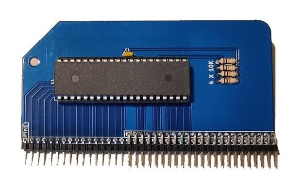
Z80 CPU v2.1
This could be classified as the ‘brains’ of the system as it contains the Z80 processor
There are not many parts to solder, the biggest amount of soldering is the 40 pin IC socket and the header for the bus.
There are 4 resistors, 1 0.1uF capacitor, IC socket and header. That’s it once you have soldered the IC socket you can fit the Z80 processor, you should observe ESD measures and carefully straighten the Z80 pins to carefully push it into the socket.
Alternatively you can purchase a ZIF socket but that’s an extra expense and it will stick out a bit further than a standard socket
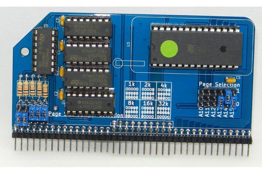
RC2014 Pageable ROM Module
This module offers more features including the option of paging itself out and paging the lower half of the 64K RAM Module in for a full 64k RAM
- Support for a huge amount of EPROMS – 2716, 2732, 2764, 27128, 27256, 27512 (2K, 4K, 8K, 16K, 32K, 64K) ROM, PROM, EPROM or EEPROM
- ROM pages of 1k, 2k, 4k, 8k, 16k or 32k on logical boundaries can be addressed through jumpers
- When used with 64K RAM Module, paging out the ROM will enable the lower 32k of RAM
The PROM supplied with the standard kit has Microsoft BASIC for a 32k RC2014 supplied in the first 8k. This leaves 56k spare for you to use for your own purposes.
If you wish to purchase one with this kit you have 3 different options;
- 00000000 Blank (64k available for your use)
- R0886099 32k BASIC, SCM and CP/M for 68B50 serial
- 24886009 32k BASIC, 56k BASIC, SCM and CP/M for SIO/2 serial
There are more parts to solder – 5 TTL IC sockets, 1 EPROM socket, 5 resistors and 5 decoupling caps and the header. Again all the parts are through hole and not difficult to solder.
You need to carefully straighten the IC pins and then fit them in the sockets.
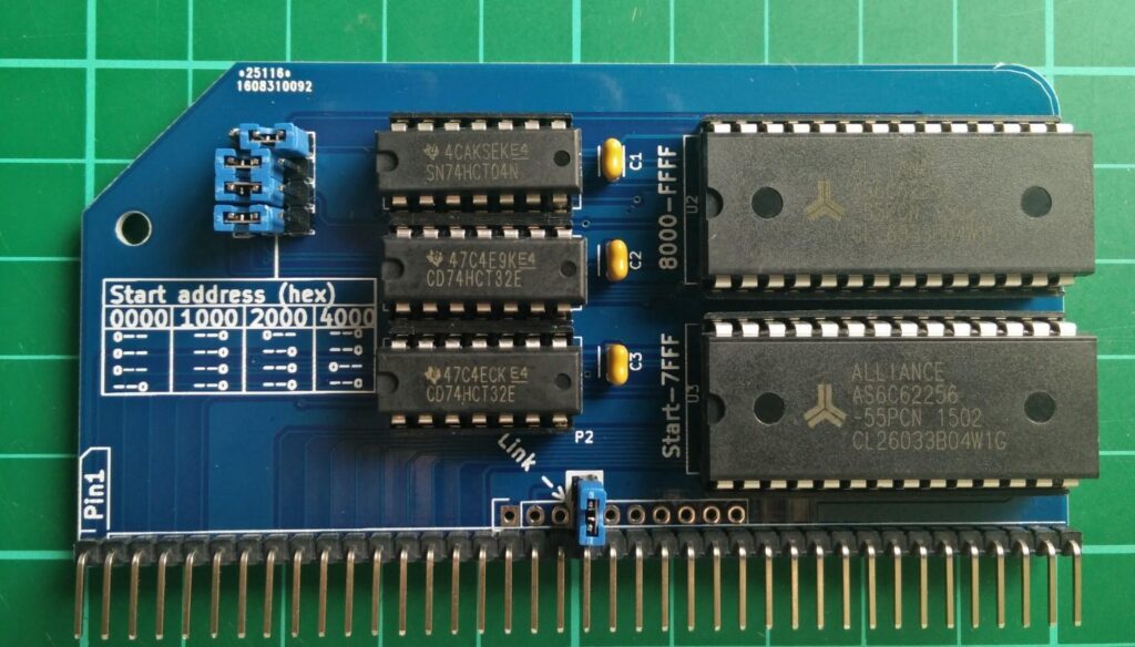
64k RAM Module
The 64k RAM module uses 2 62256 static RAM chips for up to 64k of RAM in the RC2014. Jumpers allow you to set it to only 32k, 48k, 56k or 60k if you wish so you can use 32k, 16k, 8k or 4k of ROM, and a page pin allows for the lower 32k to be disabled.
You get 2 x 28 pin IC sockets, 3 x 14 pin IC sockets to solder and a 39 pin header. There are 3 100nf decoupling capacitors
You then fit the 2 x 74LS32, 1 x 74LS04 to the 14 pin sockets and the 2 x 62256 RAM into the 28 pin IC sockets. You will have to straighten the legs of the ICs and observe ESD precautions for the RAM chips
The instructions online give details of the addresses
Links
I don’t get anything from this but appreciate hard effort and work put in – so if you want to look at the various products on offer, visit


