An AND gate is one of the basic building blocks in digital electronics and logic design.
This tutorial explains the functionality, truth table, symbolic representation, and applications of the AND gate with examples.
What Is an AND Gate?
The AND gate is a basic logic gate that implements the logical conjunction (AND operation) of two or more input signals.
It outputs 1 (true) only when all its inputs are 1 (true); otherwise, the output is 0 (false).
AND Gate Symbol
- Standard Symbol: The AND gate is represented by a D-shaped symbol in logic circuit diagrams.
- Inputs and Output:
- It typically has two or more input signals.
- It has a single output signal.
Two-Input AND Gate Symbol
       A ----|     |
             | AND |---- Y
       B ----|     |
Three-Input AND Gate Symbol
       A ----|     |
       B ----| AND |---- Y
       C ----|     |
AND Gate Truth Table
The truth table shows how the output of the AND gate behaves based on its input signals.
Two-Input AND Gate Truth Table
| Input A | Input B | Output Y |
|---|---|---|
| 0 | 0 | 0 |
| 0 | 1 | 0 |
| 1 | 0 | 0 |
| 1 | 1 | 1 |
Three-Input AND Gate Truth Table
| Input A | Input B | Input C | Output Y |
|---|---|---|---|
| 0 | 0 | 0 | 0 |
| 0 | 0 | 1 | 0 |
| 0 | 1 | 0 | 0 |
| 0 | 1 | 1 | 0 |
| 1 | 0 | 0 | 0 |
| 1 | 0 | 1 | 0 |
| 1 | 1 | 0 | 0 |
| 1 | 1 | 1 | 1 |
AND Gate Logic Expression
The logical expression for an AND gate is:
| Boolean Expression Y = A.B | Read as A AND B gives Y | ||
For a three-input AND gate:
| Boolean Expression Q = A.B.C | Read as A AND B AND C gives Q | |||
AND Gate Operation
The AND gate performs the multiplication operation for binary numbers. Here’s how it works:
- If all inputs are 1, the product is 1.
- If any input is 0, the product is 0.
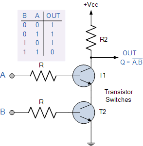
Constructing an AND Gate Using Transistors
Transistor-Level Implementation
- NAND Gate-based Design:
- An AND gate can be constructed using two NAND gates.
- Direct Design:
- The AND gate can be directly constructed using diodes and transistors.
- Transistors are arranged in series, allowing current to pass through only when all inputs are high (1).

Applications of AND Gate
- Control Circuits:
- Used to control the operation of devices, ensuring actions occur only when multiple conditions are satisfied.
- Decision Making:
- AND gates are part of decision-making circuits in microprocessors.
- Arithmetic Circuits:
- Used in binary multiplication and combinational circuits like adders.
- Password Checking:
- If all required conditions (e.g., correct username and password) are met, the output grants access.
- Traffic Light Systems:
- To turn on a green signal, multiple conditions (like no pedestrian crossing) must be satisfied.
AND Gate Using ICs
Popular ICs for AND Gates
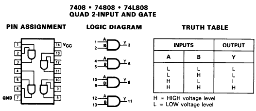
- IC 7408:
- A quad 2-input AND gate IC.
- Contains 4 independent AND gates with 2 inputs each.
- Pin Configuration of IC 7408:
| Pin Number | Function |
|---|---|
| 1, 2 | Input A, Input B (Gate 1) |
| 3 | Output Y (Gate 1) |
| 4, 5 | Input A, Input B (Gate 2) |
| 6 | Output Y (Gate 2) |
| … | … |
| 14 | VCC |
| 7 | GND |
Commonly available digital logic AND gate IC’s include:
TTL Logic AND Gate
- 74LS08 Quad 2-input
- 74LS11 Triple 3-input
- 74LS21 Dual 4-input
CMOS Logic AND Gate
- CD4081 Quad 2-input
- CD4073 Triple 3-input
- CD4082 Dual 4-input
AND Gate in Boolean Logic
- Simplification: Used in Boolean algebra to simplify logical expressions.
- Example: Simplified: Y=A⋅B⋅C
Summary
- The AND gate is a fundamental digital logic gate that outputs 1 only if all inputs are 1.
- It is widely used in combinational circuits for decision-making, arithmetic operations, and control logic.


